RECTIFIERS
Rectifier:
It is a device which converts a.c. voltage to d.c. voltage by allowing a current to flow through it in one direction.
It is classified into 2 types:
(i) Half Wave Rectifier(H.W.R)
(ii)Full Wave Rectifier(F.W.R)
(i) HALF WAVE RECTIFIER:
It is a simple rectifier made with one diode. When the voltage of the alternating current is positive, the diode becomes forward-biased and current flows through it. When the voltage is negative, the diode is reverse-biased and the current stops.Hence, the output wave form of H.W.R has only 1 half cycle and the remaining half cycle is blocked.
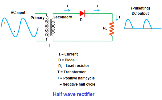
As a result, nearly half of the applied power is wasted in half wave rectifier. In addition to this, the output current or voltage produced by half wave rectifier is not a pure DC but a pulsating DC which is not much useful.
(a)RMS ( Root mean squared) value of current:
Irms=Im2
(b)Rectifier efficiency:The rectifier efficiency determines how efficiently the rectifier converts alternating current(AC). It is defined as the ratio of the DC output power to the AC input power.
ᵑ = DC output powerAC input power = PDCPAC
High rectifier efficiency indicates a most reliable rectifier while the low rectifier efficiency indicates a poor rectifier.
(c) Ripple factor: It is defined as the ratio of RMS value of current to the DC component of the current.
γ=Irms2IDC2-1
It measures the smoothness of the output DC signal.
The output signal with less ripples is known as smooth DC signal while the one with more ripples is known as pulsating DC signal.
Ripple factor for H.W.R is very high and hence it is a poor converter into A.C. to D.C.
(d) Peak Inverse Voltage(PIV): It is the max. voltage that a diode can withstand in reverse bias.
PIV of diode= Esm
(ii) FULL WAVE RECTIFIER:It allows the electric current during both positive and negative half cycles of the input AC signal.Hence, the DC output of the FWR is double of that of HWR. 
(a)RMS ( Root mean squared) value of current:
Irms=Im2
(b)Rectifier efficiency:
ᵑ = DC output powerAC input power = PDCPAC
(c) Ripple factor:
γ=Irms2IDC2-1
FWR contains very few ripples. Hence its DC output signal is smoother than that of HWR.
(d) Peak Inverse Voltage(PIV): It is the max. voltage that a diode can withstand in reverse bias.
PIV of diode=2 Esm
RECTIFIERS WITH FILTERS
Filter circuits are used to minimize the ripples in the D.C. output signal. It uses two components mainly--- inductance and capacitance. Capacitance is connected parallel to the load( as it blocks d.c when connected in series).
It is classified into 4 types—
- Inductor filter : It is also called choke filter. The inductor is inserted between the rectifier and load resistance RL. Only the DC component reaches the load.

- Capacitor filter: Here, the capacitor is connected in parallel to the load resistor.

Ripple voltage , Vr = EDC2fCRL where Vr is ripple voltage. ( For full wave peak to peak ripple)
Vr(rms)= Vr23
Ripple factor= Vr(rms)EDC= 143fCRL ( For full wave)
Vr = EDCfCRL (For half wave peak to peak ripple)
Ripple factor= Vr(rms)EDC= 123fCRL ( For half wave)
(iii)LC filter: In inductor filter, the ripple factor is directly proportional to load resistance. While in capacitor filter, it varies inversely with load resistance. Hence,on combining both, the ripple factor will almost become independent of load resistance.

(iv) π filter: It consists of one inductor and two capacitor connected across its each end. The three are arranged in the shape of the Greek letter “pi” and hence the name. It is used for low current equipments.

Srinidhi Sripada(57)

